Additional wear out of tolerances can result in additional unplanned downtime costs, so it is important to estimate the number of parts that represent tool durability before deciding on tool material and production. The basis of digital simulation is the theory of quantitative and qualitative aspects of the wear rate of forming tools. Wear is described in the forming technique by contact mechanical models. The Achard wear model is best described for this feature. The wear amount W is described in relation to the wear coefficient K, the standard force Fn2, the wearer hardness H, and the grinding range s.
The wear factor K, which includes multiple influences, such as lattice structure and fracture toughness, cannot be included in the digital simulation of tool wear by boundary conditions.
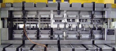
Test tool mounted on automatic punch press
Wear process simulation
The wear simulation program Redsy developed by the molding technology and casting department of the University of Technology of Mohne is able to quantitatively and qualitatively calculate the degree of tool wear during sheet metal forming. The authors have been able to demonstrate that a forming simulation combined with a wear simulation based on the Achard model, the calculated wear is highly consistent with the amount actually formed. In order to obtain the best calculation quality with this algorithm, it is necessary to specifically measure the wear coefficient of the pair of plates and tool materials used.
Wear measurements for important tool materials and sheet pairs form the basis for a correct quantitative wear simulation. The test was carried out taking into account the material pairing of the overall friction system. To maintain its boundary conditions, such as the oil supply state and speed profile is stable. To date, most of the wear tests have been carried out in the stripping test and the groove test of the changing steel strip. The key limitation of the so-called inspection method is that the deformation of the sheet material or the force is not uniform on the actual forming tool. The causes are creases, sheet thickness, traction and surface pressure caused by head pressure. Accuracy can be improved by a combination of simulation and molding tests. The above-mentioned wear inspection method can directly measure the wear parameters in the deep drawing process and greatly improve the calculation quality of the wear simulation software.
A rotationally symmetric disk is used for the wear test, which is built on an 8-station progressive die. Using the digital graphics of the deep-drawing process to compensate for the measurement results, the wear coefficient of the various material pairs can be derived.
The tool is used on a high-efficiency automatic press (Typ BSTA125 BL, Bruderer) with a 60-stroke/min punch with a lift of 75 mm.
Considering that the punching dynamics will produce a collision speed of 0.2 m/s, it is very important to use an automatic press because the punching force and working ability it provides are sufficient for the splitting and forming operations.
The sheet is machined into a 100 mm wide steel coil. The automatic feeding speed is 93.2 mm per punching lift, and the crank angle is within 45° of the upper stroke transition point. Four modules of the progressive die were used during the test.
Model makes wear more clear
In the modules 1 to 3, the strip was cut into thin slabs, and deep drawing was performed in the module 4, so the wear test analysis of the active components was performed on this module. The 5 to 7 modules have no work. This is necessary for realistic sheet metal advancement in view of the tool structure. In the module 8, the steel strip is finally separated, and the necessary platen force is fed through the gas spring in the 1 to 4 modules. There is a waiting site between modules for structural reasons. The wear measurement is performed on the die side of the module 4, because in this position, a large amount of wear is estimated to occur due to the forming process and the sliding punching surface. The other active components were placed on tool steel Typ X155CrVMol 12.1 (1.2379) and were not replaced during the experiment. In order to obtain as much detailed data as possible about the wear state of the material being tested, it is not only measured at the end of the test, but the measurement interval can be selected depending on the material.
Since the measurement accuracy is usually very high, the wear measurement is performed with 2 different measuring instruments. In addition to a Gom company's optical surface digital Gom Atos II 400 (measuring noise of about 8mm), there is also a metronome shaped cutting measurement system (Typ Mahr Surf XCR20, Mahr GmbH).
The measurement accuracy of this type of metrology measurement method is in the micrometer range (measurement noise is about 0.5 mm), so that reliable data can be obtained even with a small amount of wear.
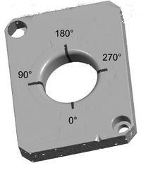
Fig. 2 Measurement points of the beat type profile measurement on the die (dark) and the groove of the digital die surface on the surface of the steel plate
The die entrance radius is obtained at 4 points by means of profile measurement. These are clear and can be obtained repeatedly and accurately. For this purpose, the die is placed in a device that is inclined by 45° with respect to the horizontal. The measurement points are distributed at 0°, 90°, 180° and 270° in the hole of the die as seen from the direction in which the steel sheet is advanced.
The tool materials GGG70L (0.7070L, 40HRC), GS60 (1.0558, 50HRC) and X155CrVMol12.1 (1.2379, 63HRC) were tested under tempering or vacuum hardening. The tool is uncoated and the surface is polished. The oil supply system uses Multidraw KTL-N1 (Zeller+Gmelin GmbH & Co. KG, Eislingen/Fils) to supply oil from both sides (about 2 g/m2) by means of a spray tank.
Used as sheet metal, DC05 (DC05+ZE75/75-BO, thickness 0.8mm, electrolytic galvanizing, 6 t), HC380LAD (HC380LAD+Z100BMO, thickness 1.0mm, hot-dip galvanizing, 13 t), and HC400TD ( HC400TD+Z100BMO, plate thickness 1.0mm, hot-dip galvanized, 18 t). Sheets relate to pitch materials used in the automotive industry, from soft drawn materials to high hardness Trip steels.
By optimizing the oil supply and air cooling the tool, the friction between the materials can be affected, so that zinc wear does not adhere to the tool during the experiment.
Various material pairing results
In order to describe the condition of the sheet, both the structural photomicrograph and the surface REM photograph were taken. The surface of the sheet with superior friction properties shows a clear difference, and these differences are reduced after finish rolling. The HC400TD sheet has a very structured pocket-shaped hole that enters the hole through a statically sealed, sealed seal to adjust for good friction conditions. However, the surface of other sheets is not the case because the sheet has an open lubrication pocket and a large contact surface to prevent the formation of a bearing lubricant film.
The wear rate of all material pairs was documented. The measurement interval is determined according to the material, and it is expected that the measurement interval is relatively large when the wear amount is relatively low. The strength values ​​of the plates vary widely, and they sense different loads of the tool during deep drawing.
Once the hardness of the tool material exceeds the hardness of the board, the mechanical properties of the wear deposits can determine the process. This is true in all tests with a tool hardness of >40 HRC, so hard tools require relatively soft sheet wear. The HC400TD sheet exhibits good friction properties because a lubricious cushion layer can be formed based on surface properties. Although the mechanical load of the tool is high during the forming process, the wear rate of the material pair using the plate is low.
It is noted that this boundary condition can be determined not only by the strength of the sheet but also by the frictional properties that will significantly affect the tool wear. High-strength sheets with good friction properties can detect less wear than soft sheets with poor friction properties.
Friction ratio affects wear
It is concluded that the surface friction of the sheet is largely related to the wear characteristics during deep drawing. All effects such as lubricant, amount of lubrication, temperature, surface roughness and surface structure are added to this intricate frictional transformation.
The following amount of wear coefficient was calculated from the wear measurement: the wear depth w [mm] of any generated value was generated from the measurement. The integration and wear work of the contact pressure and the sliding speed can be determined by means of the FE-simulation and the Redsy calibration procedure. The hardness of the tool material can also be obtained from the test.
To illustrate the efficiency of the above method, an exemplary wear simulation experiment was performed for material pairing DC05-GS60. The material paired wear coefficient K = 2.035E-7 was obtained in the wear measurement test. The wear simulation program Redsy uses this factor to calculate the wear pattern listed in Figure 3b.
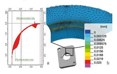
Figure 3 Material Pairing DC05-GS60: Die Entry Radius Beat Profile Measurement (2) and Redsy (b) Wear Simulation Results after 25000 Lifts
A comparison with the die entrance radius beat profile measurement (Fig. 3a) shows that the simulation results are in good agreement with the measurement results in both quantity and quality. The maximum wear of the two sets can overlap each other in position and depth.
The above method based on simulation support wear calculation is a new method for experimentally measuring the wear coefficient. Pairing the experimental materials indicates the wear process and the resulting wear factor. Special attention should be paid to the wear state of the board being inspected. In addition to sheet strength, the friction ratio also significantly affects tool wear. High-strength sheets with good friction properties can detect less wear than soft sheets with poor friction properties.
It is concluded that the surface friction of the sheet is largely related to the wear characteristics during deep drawing.
Extending tribology with wear models
The first results of the wear simulation software Redsy based on the measurement were quite consistent with the experimental results. Since the friction properties of the sheet are experimentally and integrated into the wear coefficient, accurate conclusions about the quality of the wear state of the material pair can only be of general significance when the wear model is extended to the description of the friction performance.
The key results of the work presented here were obtained in the “Abrasion Calculation of Plate Forming Process, Simulation Support for Wear Calculation†(AiF14291N) research project.
The research project was supported by the Federal Ministry of Economics and Labor's budget for the Industrial Research Federation Labor Committee “Otto von Guerickeâ€.
Casing Pipe,Steel Casing Pipe,Welded Steel Pipes,Astm Casing Pipe
Torich International Co.,Ltd--The Steel Tube Maker , http://www.chinasteeltubepipe.com