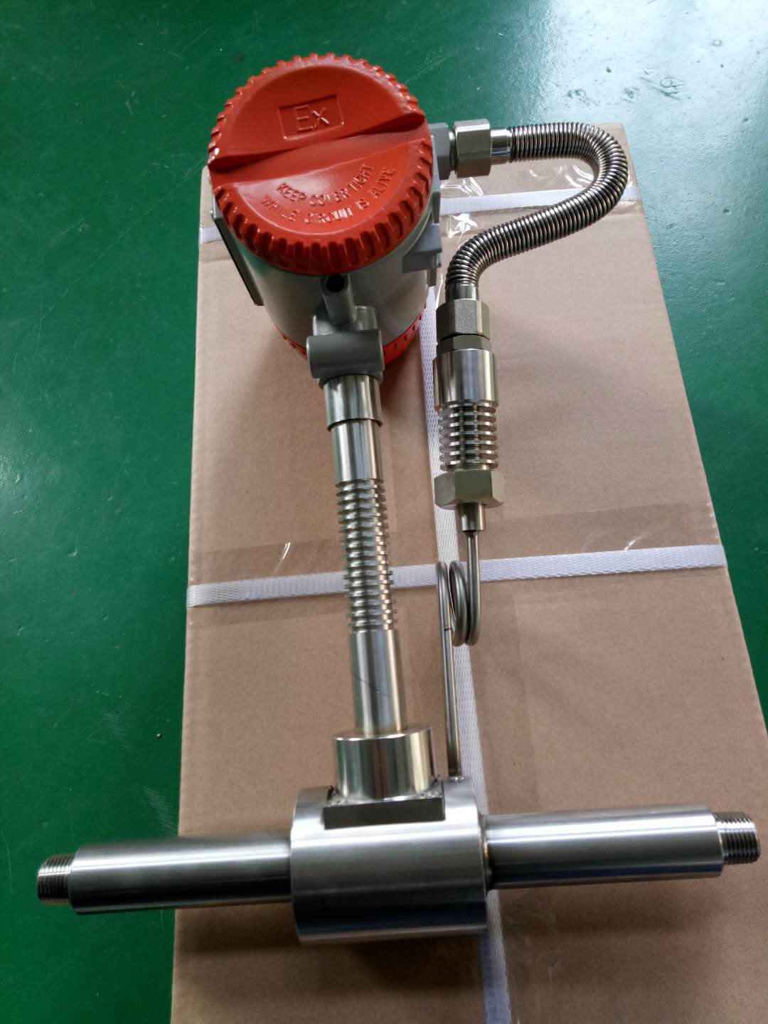
What are the installation skills of LUGB vortex flowmeter

LUGB vortex flowmeter measures volumetric flow of gas, steam or liquid, standard volumetric flow or mass flow. Mainly used for flow measurement of industrial pipeline medium fluid, such as gas, liquid, steam and other media.
1. The intelligent vortex flowmeter can only measure in one direction, and pay attention to ensure that the direction of the medium flow is consistent with the direction of the arrow of the flowmeter during installation.
2. The best installation method for LUGB vortex flowmeter is vertical installation, and the medium passes through the flowmeter from bottom to top. That is, the flowmeter is installed on a vertical pipe with the flow direction from bottom to top.
3. When installing horizontally, the flowmeter must be installed in the high-pressure area of ​​the entire system, and the corresponding outlet pressure must be ensured; do not install it at the highest point of the pipeline, because the highest point tends to accumulate gas, the pipeline is not full, and the outlet cannot be directly Short.
LUGB vortex flowmeter
4. When measuring high temperature fluid, try to use vertical installation method; if you have to install horizontally, please install the transmitter part of the flowmeter vertically down or horizontal side to avoid excessive temperature; pay attention to the air flow at the installation location Or well ventilated.
5. Straight pipe section requirements: at least 15 times the pipe diameter before the flowmeter and 5 times the pipe diameter behind the flowmeter. If there are elbows, indentation, expansion and other interference sources in front of the flowmeter, you need to ensure that the pipe diameter is 30-40 times before the flowmeter and 6 times the pipe diameter after the flowmeter. The flowmeter should be installed upstream of the regulating valve, pressure or temperature sensor. 6. When installing, pay attention to the pipe diameter should be slightly greater than or equal to the inner diameter of the instrument. 7. When using the seal ring, pay attention that the inner diameter of the seal ring should be slightly greater than or equal to the inner diameter of the instrument, and the center of the seal ring is located in the center of the pipeline.
Cable inlet seal of intelligent vortex flowmeter
When the instrument is electrically connected, attention must be paid to the sealing of the inlet hole. The corresponding sealed interface (M20Χ1.5; 1/2 "NPT; G1 / 2") must be selected according to the instrument cable entry model, and installed correctly and tightly. Without sealing joints, or installing sloppy, can not achieve the sealing effect, is one of the most common causes of instrument damage.
LUGB vortex flowmeter

The Installation of Mounting Unit
1. Make the concrete base according to solution drawing, locate embedded bolts and set out strings by Laser Level to ensure the centers of embedded bolts in the same elevation as accurate as possible on vertical, horizontal direction and at end face.
2. Locate the Anchor Plate on the concrete base and adjust the position according to solution drawing(remove M14 washer,M14 spring washer,and M14 nut if they are connected to embedded bolts now),and then fasten M14 washer, M14 spring washer, and M14 nut with the tightening torque of 60N.m.
3.Take out the Hexagon Bolt Kit with Post B Corrugated Gasket M12x95 and remove its nut, spring washer, one washer, and corrugated gasket. Insert the Post A, B, C in to Anchor Plate according to the Hexagon Bolt Kit with Corrugated Gasket M12x95 drawing and then fix them by two sets of Hexagon Bolt Kit with Corrugated Gasket M12*95. Post C Post A
4.Remove the bolt kits M12*90 from all the Posts and Pre-Assembled Supports and unfold the embedded Supports, fasten them on the Posts by bolt kits M12*90 according to the drawing. 

Installation of Rails
1.Please check the length of Beam before place it onto the Pre-Assembled Supports, otherwise extend it with Splice forBeam first. There are 4 self-tapping screws in each side and total 8 self- tapping screws in both sides. We strongly recommend NOT extend the Beams on Preassembled Supports.
2.Before locate the Beams, mark the position of the Beam son the surface of Pre-Assembled Supports with maker pens according to solution drawing for easier installation. Place the Beams on the 55*80 Tube of Pre-Assembled Supports and fix it with C Clamp Kits. Install all the Beams in the same step. The tightening torque will be 20N.m. C Clamp Kit Side Beam(Please arrange 3-4 persons to install when the array is long.)

Installation of Solar Panels
1.Place the panels above the Beam 85, fixing it with Wide End Clamp Kit in the side and Inter Clamp Kit in the middle. Install all the panels in the same steps until complete installation of al panels. Fasten all the bolts with tightening torque of 10N.m.
2.Complete installation, and please inspect and make sure all the bolts are fastened.

Solar Mounting System For Green House

Solar Panel Mounting Frames,Solar Panel Mounting Systems,Greenhouse Solar Mounting System,PV Mounting Systems

Hebei Honde Plastic & Metal Co., Ltd. , https://www.foundation-system.com