Summary of Research on Mortar Wire Cutting Technology (1)
Abstract: This paper provides an in-depth analysis of the principle behind mortar wire cutting, the tension control system, the performance and recycling of the cutting slurry. It also highlights the current limitations in research, aiming to promote further development of this technology and guide practical applications in the industry.
Introduction
Silicon-based materials are currently the primary material used in photovoltaic cells, with silicon-based solar cells accounting for over 85% of global photovoltaic production. Crystalline silicon wafers, as the front-end product of the solar photovoltaic industry, play a crucial role in the entire supply chain. Multi-wire cutting is commonly divided into two types: mortar wire cutting and diamond wire cutting. Among these, mortar wire cutting remains the dominant method for silicon wafer production. It involves a mixture of silicon carbide (SiC) and a cutting fluid, typically polyethylene glycol (PEG), which forms a slurry. This slurry, under pressure between the steel wire and the silicon rod, causes plastic deformation and cracking on the surface of the silicon rod, resulting in a cut [1]. As the photovoltaic industry continues to grow, the demand for higher-quality silicon wafers increases, prompting deeper research into wire cutting technologies.
This paper explores various aspects of mortar wire cutting, including the mechanism and model of the process, the types and future directions of tension control systems, factors influencing slurry performance, and methods for controlling it. Additionally, it discusses the recovery and reuse of the slurry, aiming to support more advanced research and improve real-world production processes.
1. Research on Cutting Mechanism
In the process of cutting a silicon rod using a mortar wire, silicon carbide particles perform a "rolling-indentation" action between the silicon rod and the steel wire, enabling material removal [2]. Shu Jiqian et al. [3] have thoroughly analyzed the cutting mechanism, including the single-particle rolling-indentation model, multi-particle indentation effect model, and elastic-fluid effect model. Yu et al. [4] simulated the cutting force of the single-particle model, as shown in Figure 1. From this simulation, they derived a formula for calculating the normal cutting force N.
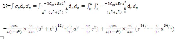
(1) where: ε is the maximum cutting depth; a is the contact length; Ï… is Poisson's ratio; E is Young’s modulus; ζ = z / a, Ï = r / a; μ is the friction coefficient, and other terms are constants.
 (2)
(2)
 (3)
(3)
The tangential cutting force can be calculated from the normal cutting force using the following equation:
 (4) where: β = cos θ is a dimensionless coefficient.
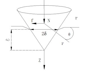
Figure 1 Schematic diagram of the force of single-particle silicon carbide
Furthermore, simulations using finite element software were conducted to analyze the effects of different cutting speeds and feed rates on stress and strain. The results showed that the maximum stress and strain in the cutting zone are inversely proportional to the feed rate, while both are directly proportional to the cutting speed.
Solar Charging Lamps, Led Emergency Bulbs, Handheld Flashlight Emergency Light
Guangdong Dp Co., Ltd. , https://www.dp-light.com