1 Scope
This standard stipulates the definition, composition, requirements, test methods, inspection rules, and packaging, storage and transportation of solar power systems for communications.
This standard is applicable to off-grid photovoltaic power generation systems or hybrid power generation systems that supply power to communication equipment. It does not apply to power generation devices such as photovoltaic power generation systems and diesel generator sets that supply power to the grid.
2 normative references
The clauses in the following documents have been adopted as references to this standard. For dated references, all subsequent amendments (not including errata content) or revisions do not apply to this standard, however, encourage the parties to reach an agreement based on this standard to study whether the latest version of these documents can be used . For undated references, the latest version is applicable to this standard.
GB/T 191-2008 Packaging, Storage and Transportation Icon Mark (ISO 780:1997, MOD)
GB/T 2423.1-2008 Environmental testing for electric and electronic products Part 2: Test methods Test A: Low temperature (IEC 60068-2-1:2007, IDT)
GB/T 2423.2-2008 Environmental testing for electric and electronic products Part 2: Test methods Test B: High temperature (IEC 60068-2-2:2007, IDT)
GB/T 2423.3-2006 Environmental testing for electric and electronic products Part 2: Test methods Test Cab: Constant moisture heat test (IEC 60068-2-78:2001, IDT)
GB/T 2423.10-2008 Environmental testing for electric and electronic products Part 2: Test methods Test Fc: Vibration (sinusoidal) (IEC 60068-2-6:1995, IDT)
GB/T 2828.1-2003 Count sampling inspection procedure Part 1: Batch inspection sampling plan (ISO 2859-1:1999, IDT) searched by acceptance quality limit (AQL)
GB/T 3873-1983 General technical conditions for product packaging of communication equipment
GB/T 4980-2003 Determination of noise in positive displacement compressors
GB/T 6495.3-1996 Photovoltaic devices - Part 3: Measurement principles and standard spectral irradiance data for terrestrial photovoltaic devices (IEC 904-3:1989, IDT)
GB/T 9535-1998 Design and identification of crystalline silicon photovoltaic modules for ground use (eqv IEC 1215:1993)
GB/T 20626.1-2006 Special environmental conditions Plateau electrical and electronic products Part 1: General technical requirements
YD/T 122-1997 Nameplate of Post and Telecommunications Industry Products
YD/T 282-2000 General Test Method for Reliability of Communication Equipment
YD/T 637-2006 DC Direct Current Conversion Equipment for Communication
YD/T 777-2006 Inverter Equipment for Communication
YD/T 799 Valve Controlled Lead Acid Battery for Communication
YD/T 944-2007 lightning protection technical requirements and test methods for communication power supply equipment
YD/T 983-1998 Electromagnetic Compatibility Limits and Measurement Methods for Communication Power Equipment
YD/T 1360 Valve-controlled Sealant Battery for Communication
YD/T 1363.3-2005 Power Supply, Air Conditioning and Environment Centralized Monitoring and Management System for Communications Bureau (Station) Part 3: Front-end Smart Device Protocol
IEC 60896-11 Fixed Lead-Acid Batteries Part 11: Vented - Requirements and Test Methods
3 Terms and Definitions
The following terms and definitions apply to this standard.
3.1
Rated output current of photovoltaic power system
The solar cell array undergoes a rated DC output current converted by the controller.
3.2
Wind power system rated output current of wind energy system
The rated DC output current of the wind turbine after conversion by the controller.
3.3
Step-by-step type solar power system
Through a series of solar cell modules (matrix), one by one casts and withdraws to achieve a stabilized solar power system.
3.4
Pulse width modulation type solar power system
By adjusting the duty cycle of the control element switching pulse to achieve a stable solar power system.
3.5
Transformer-controlled solar power system DC/DC mode photovoltaic power system
The regulated DC solar power system is achieved by a DC-DC converter.
4 Solar Power System Composition
4.1 System Composition
The system consists of a solar array (including brackets), batteries (sets), controllers (including voltage regulators and power distribution units or interfaces with other power systems), and inverters (optional).
4.2 Product Classification
4.2.1 divided by controller type
According to the type of controller, the solar power system can be divided into step-by-step type, pulse width modulation type, and conversion voltage type.
4.2.2 According to system components
According to the components of the system can be divided into:
- Independent solar power system;
- A solar-powered complementary power system;
- Solar-diesel generator complementary power supply system;
- Wind and solar power systems;
- Other hybrid power systems.
4.3 The composition of the system
4.3.1 Independent Solar Power System
The composition of an independent solar power system is shown in Figure 1.
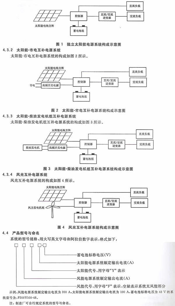
4.5 series
4.5.1 DC output voltage nominal value
12V, 24V, -48V.
4.5.2 Rated output current value of solar power system
10A, 20A, 30A, 50A, 100A, 200A, 300A, 500A.
Note: When users request and consult with the manufacturer, they can produce products other than series values.
5 requirements
5.1 Environmental Conditions
5.1.1 Normal Conditions of Use
Normal use conditions are as follows:
——Working environment temperature of outdoor equipment: -30°C to +55°C;
- Indoor equipment working environment temperature: -5 °C +40 °C;
- Battery working environment temperature: -15°C +40°C;
——Working environment humidity of indoor equipment: not more than 90% RH.
Note: When the ambient temperature is lower than -20°C, heat preservation measures shall be adopted for the battery (group); when the working environment temperature exceeds the above range, the technical conditions are negotiated between the user and the manufacturer.
5.1.2 Storage and Transportation Conditions
Storage and transportation conditions are as follows:
- Storage and transportation environment temperature of battery: -20°C +40°C;
- Storage and transportation environment temperature of other equipment: -40°C to +70°C;
- Storage and transportation environment humidity: no more than 90% RH.
5.1.3 Atmospheric pressure
The atmospheric pressure range is (70-106)kPa; when the atmospheric pressure is below 70kPa, the technical conditions are negotiated between the user and the manufacturer. The manufacturer can design and produce according to the requirements of GB/T 20626.1-2006.
5.1.4 Vibration
The system shall be able to withstand sinusoidal vibration with a frequency of (10-55) Hz and an amplitude of 0.35 mm.
5.2 Solar Modules and Matrix
5.2.1 Basic requirements
Solar modules should comply with the provisions of GB/T 9535-1998.
5.2.2 Peak power
The deviation of the peak power of the solar cell module from the nominal value should be in the range of 0-3%.
5.2.3 Conversion efficiency
The conversion efficiency of solar cells should not be lower than 13%, and the conversion efficiency of solar cell modules should not be lower than 11%.
5.2.4 Feeder loop voltage drop
When the solar cell array output rated current, the voltage drop of the feeder circuit from the solar cell array to the controller input terminal should not exceed 5% of the nominal value of the system DC output voltage.
5.3 Battery
5.3.1 Basic requirements
Valve-regulated sealed lead-acid batteries shall meet the general requirements of YD/T 799, valve-regulated sealed colloidal batteries shall meet the general requirements of YD/T 1360, and flood-proof acid-proof explosion-proof batteries shall comply with the general requirements of IEC 60896-11. .
5.3.2 High temperature performance
When the battery is under 40°C ambient conditions, the discharge capacity should not be less than 100% of the rated capacity (C10).
5.3.3 Low temperature performance
The discharge capacity of the battery should not be lower than 75% of the rated capacity (C10) under the environmental condition of -5°C.
5.3.4 Battery Capacity Recovery Performance
After 5 short-circuit cycles of the battery, the discharge capacity is not less than 90% of the rated capacity (C10).
5.3.5 cycle life
According to the test method specified in 6.2.5, the cycle time of valve-regulated sealed lead-acid batteries shall not be less than 600, that is, not less than 4 cycles; the cycle time of valve-controlled sealed colloidal batteries shall not be less than 900, ie The cycle is not less than 6 times; the cycle time of the flooded acid-proof and acid-proof explosion-proof battery is not less than 1 500 times, that is, the cycle is not less than 10 times.
5.4 Controller
5.4.1 Appearance and Structure
Shell panels should be flat, strong plating, corrosion protection coating uniformity; all marks, signs clearly legible, no peeling, rust, cracks, obvious deformation; can be wall-mounted, embedded or floor-mounted installation, should Solid and reliable.
5.4.2 Input Voltage Range
When the input voltage changes within the output voltage range of the matching solar array, the controller should be able to work normally.
5.4.3 DC Output Shunts
The DC output branch of the DC power distribution unit and the battery circuit shall have overcurrent or short circuit protection devices such as circuit breakers of appropriate capacity.
5.4.4 DC Distribution Unit Discharge Circuit Voltage Drop
When the system outputs the rated current, the voltage drop of the battery discharge loop of the DC power distribution unit should not exceed 500mV (ambient temperature 20°C).
5.4.5 Lightning Protection Requirements
The solar cell array input end of the controller shall be equipped with a surge protection device, which shall meet the requirements of YD/T 944-2007.
5.4.6 step by step controller
5.4.6.1 Input/Removal Voltage
The step-by-step investment type controller shall have the function of throwing in/out part or the entire solar cell square array, and the voltage of the withdrawal square matrix shall not be higher than 120% of the nominal value of the DC output voltage, and the voltage of the investment square matrix It should not be less than 110% of the nominal value of the dc output voltage.
5.4.6.2 Charge and discharge loop voltage drop
When the system outputs the rated current, the voltage drop of the charging and discharging circuit (including the DC power distribution unit) of the step-by-step human-type controller shall not exceed 5% of the nominal value of the DC output voltage.
5.4.7 Pulse Width Modulation Controller
5.4.7.1 Charging voltage
Pulse width modulation type controller should be able to carry out floating charge, charge and manual and automatic conversion according to the state of the battery, and the float voltage should be able to be in the direct current input.
The nominal value of the output voltage is adjusted between 90% and 113%. The average charging voltage should be adjustable between 115% and 120% of the nominal value of the DC output voltage.
5.4.7.2 Charge and discharge loop voltage drop
When the system outputs the rated current, the voltage drop of the charge-discharge circuit (including the DC power distribution unit) of the pulse-width modulation type controller shall not be greater than 5% of the nominal value of the DC output voltage.
5.4.7.3 Efficiency
When the system is rated for operation, the efficiency of the PWM controller should not be lower than 90%.
5.4.7.4 Temperature Compensation
The pulse width modulation type controller should be capable of temperature compensation of the charging voltage of the battery. The adjustment range of the compensation coefficient should be (-3 to -5) mV/°C/cell, and the reference temperature is 25°C.
5.4.8 Conversion Regulator Controller
5.4.8.1 Basic requirements
The converter regulator controller uses a DC charging converter to stabilize the charging voltage. The DC-DC converter part should meet the requirements of 4.4, 4.5, 4.7 and 4.8 of YD/T 637-2006.
5.4.8.2 Charging voltage
The converter voltage regulator controller should be able to perform floating charge, manual charge and automatic conversion according to the battery state. The float charge voltage should be adjusted between 90% and 113% of the nominal value of the DC output voltage. The charge voltage should be at the DC level. The output voltage is adjusted between 115%-120% of the nominal value.
5.4.8.3 Efficiency
When the system is rated for operation, the efficiency of the switching regulator controller should not be less than 90%.
5.4.8.4 Temperature Compensation
The voltage regulator controller should be capable of temperature compensation of the charging voltage of the battery. The adjustment range of the compensation coefficient is (-3 to -5) mV/°C/cell and the reference temperature is 25°C.
5.4.8.5 Maximum Power Tracking Function
The conversion-stabilized controller with maximum power tracking function should be able to automatically adjust the output of the solar array, and if necessary, make the solar array work near the maximum output power point.
5.4.9 No-load loss
The controller's own current consumption should not exceed 1% of its rated charging current.
5.4.10 Protection Function
5.4.10.1 Reverse discharge protection
The controller should have a protection function to prevent the reverse discharge of the battery (group) through the solar cell array.
5.4.10.2 Overcurrent Protection
The controller should have automatic over load protection.
5.4.10.3 Short circuit protection
The conversion regulator controller should have a short-circuit automatic protection function.
5.4.10.4 Over and under voltage protection
Controller should have battery over-voltage protection function:
- When the battery voltage reaches the overvoltage setting value, the controller should automatically alarm and take protective measures. After the voltage drops to the set value, it should be able to automatically resume work;
- When the battery voltage reaches the undervoltage setting value, the controller should automatically alarm and take protective measures. After the voltage rises to the set value, it should be able to automatically resume work;
- The over and under voltage values ​​of the controller output voltage can be set.
5.4.10.5 Reverse Polarity Protection
The controller should have a solar battery module and battery polarity reverse polarity protection.
5.4.10.6 Impact Voltage
The controller should be able to withstand the impact of lh higher than the 1.2 times the nominal open circuit voltage of the solar cell array.
5.4.10.7 Inrush Current
The step-by-step human-type and pulse-width modulation type controller should be able to withstand an impact that is higher than 1.25 times the nominal short-circuit current of the solar module.
5.4.11 Success Function
When the system fails or enters the protection state, the controller shall issue an audible and visible alarm signal.
5.4.12 Monitoring Function
The controller should have the following main monitoring functions:
A) Real-time monitoring of power system operation status;
b) Collect and store power system operating parameters;
c) The power system can be controlled according to the commands of the monitoring and management center (optional);
d) Should have RS232 or RS485/422, IP USB and other standard communication interfaces or dry contact alarm interfaces, and provide communication cables and various alarm information output terminals for use with communication interfaces, and the communication protocol shall comply with YD/T 1363.3- The requirements of 2005 are as follows:
- Telemetry: battery voltage, battery charge and discharge current, battery temperature, load current, solar cell array and output voltage/current after controller conversion, daylight intensity (optional), ambient temperature (optional);
- Remote signaling: Battery overvoltage and undervoltage alarm, fuse/circuit breaker alarm, solar cell work state (investment/withdrawal), DC current transformer and other equipment failure (optional), lightning protection Device status (optional), controller or battery charge/discharge status (optional), secondary battery power off (optional), mains/oil unit power/wind power/solar power status;
- Remote control (optional): Float/equal charge conversion, solar cell array investment/withdrawal, diesel generator set started.
5.4.13 Display Function
The controller should be able to display: battery voltage, battery charge and discharge current, solar array square output voltage/current, load current, solar cell square array cumulative power generation (optional), load cumulative power consumption (optional), battery temperature , system work and alarm status (optional).
5.4.14 Battery (Group) Management Functions
The controller should be able to access at least 2 sets of batteries, and it should have a single voltage management function of the battery pack. When the single battery voltage is not balanced, the controller will give an alarm; if necessary, the controller should be able to adjust the charging voltage or cut off the load to avoid overcharge of the battery. Overdischarge; the controller should be able to charge the battery constant voltage current limit, the current limit value should be able to adjust within a certain range according to the battery capacity, valve-regulated sealed lead-acid batteries and valve-regulated sealed colloidal batteries, the maximum charging current of 0.25 C10A, liquid-filled, acid-proof, explosion-proof battery has a maximum charging current of 0.20C10A.
5.4.15 Secondary Next (optional)
The controller should have a secondary power off function interface.
5.4.16 Noise voltage
5.4.16.1 Telephone noise weight noise
The DC output voltage of the controller should be ≤ 2mV.
5.4.16.2 Peak-to-peak noise voltage
The peak-to-peak noise voltage in the (0-20) MH: band of the controller's DC output should be ≤200mV.
5.4.17 Audio noise
Noise during operation of the controller shall not exceed 55 dBA.
5.4.18 Security Requirements
5.4.18.1 Insulation resistance
When the ambient temperature is 15°C to 35°C, the relative humidity is less than 90%, and the test voltage is DC 500V, the insulation resistance of the AC and DC circuits to ground shall not be lower than 2 MΩ.
5.4.18.2 Electrical strength
The AC circuit shall be capable of withstanding 50 Hz, an AC voltage with an effective value of 1500 V (leakage current ≤ 30 mA) or a peak voltage of 2120 V DC for 1 min without any breakdown or arcing.
The DC circuit shall be capable of withstanding 50 Hz AC voltage with an effective value of 500 V (leakage current (30 mA) or 710 V DC voltage equivalent to its peak value for 1 min with no breakdown or arcing.
5.4.18.3 Protective Earthing
Protective grounding points should have obvious signs.
The resistance between the enclosure and all accessible dead metal parts and the protective earthing point shall not exceed 0.1Ω.
5.5 Inverter
The inverter should meet the requirements of YD/T 777-2006.
5.6 Electromagnetic Compatibility
5.6.1 Conducted disturbance limit
The conducted disturbance limit should meet the requirements of 5.1 in YD/T 983-1998.
5.6.2 Radiated disturbance limits
Radiated disturbance limits shall comply with the requirements of 5.2 of YD/T 983-1998.
5.6.3 Electrostatic Discharge Immunity
The system cabinet should be able to protect the product against electrostatic damage. Its protection capacity should meet the requirements of Table 9 “Electrostatic discharge†in YD/T 983-1998, and it should be able to withstand the impact of not less than 8kV electrostatic voltage.
5.7 Reliability
MTBF≥1×10⁵h.
6 test methods
6.1 Solar Modules and Matrix
6.1.1 Standard Test Conditions
The test uses natural light or conforms to Class A simulator in GB/T 6495.3-1996. The standard test conditions are:
- Temperature: 25 °C ± 2 °C;
- illuminance: 1000W/m2;
- Standard solar spectral irradiance: It should comply with the provisions of GB/T 6495.3-1996.
6.1.2 Basic requirements test
The basic requirements of the test method should be carried out in accordance with the provisions of GB/T 9535-1998.
6.1.3 Peak power
When the solar cell module outputs the optimal operating current, the output voltage is measured with a DC voltmeter and the product of the two is calculated. The result should meet the requirements of 5.2.2.
6.1.4 Conversion efficiency
In accordance with the provisions of GB/T 9535-1998 test, the results should meet the requirements of 5.2.3.
6.1.5 Feeder loop voltage drop
When the solar cell array outputs the rated operating current, the DC voltage meter shall be used to measure the voltage drop of the feeder circuit from the solar cell array to the controller input terminal, and the requirements of 5.2.4 shall be met.
6.2 Battery
6.2.1 Basic Requirements Test
Valve-regulated sealed lead-acid batteries are tested in accordance with YD/T 799, VRLA batteries are tested in accordance with YD/T 1360, and flood- and acid-proof explosion-proof batteries are tested in accordance with IEC 60896-11. .
6.2.2 High temperature performance
Place the fully charged battery in the thermostat, adjust the temperature to 40 °C ± 3 °C, and after the battery temperature is balanced with the ambient temperature, discharge it with I10 (A) current.
The change of the current value in the discharge process should be no more than 1%, the battery voltage should be recorded every 1h; when the voltage reaches 1.90V, it should be recorded every 5min; when the voltage reaches 1.80V, the discharge should be stopped and the discharge time should be recorded; the result should be Meet the requirements of 5.3.2.
6.2.3 Low temperature performance
The fully charged battery is placed in a thermostat and the temperature is adjusted to -5°C ± 2°C. After the temperature of the battery is balanced with the ambient temperature, the current is discharged using the I10(A) current.
The change of the current value in the discharge process should be no more than 1%. The battery voltage should be recorded every 1h. When the voltage reaches 1.90V, it should be recorded every 5min. When the voltage reaches 1.80V, the discharge should be stopped and the discharge time should be recorded. The result should be Meet the requirements of 5.3.3.
6.2.4 Battery capacity recovery performance
The test procedure is as follows:
A) The fully charged battery is discharged with I10 (A) current to approximately 0V, and its positive and negative electrodes are short-circuited and held for 24 hours;
b) After the battery is fully charged, repeat step a) for a total of 5 cycles;
c) After the battery is fully charged, discharge it with I10(A) current to 1.80V/cell. The discharge capacity shall meet the requirements of 5.3.4.
6.2.5 cycle life
The battery used for the cycle life test shall meet the requirements of 6.2.1.
The first stage (low charge, shallow cycle):
A) Put the fully charged battery into the high temperature box, adjust the temperature to 40 °C ± 3 °C, and keep it for 16h;
b) With I10 (A) current, discharge 9h or battery voltage to 1.75V, stop discharging;
c) With a current of 1.03 I10 (A), charge 3h;
d) With I10 (A) current, discharge 3h; (When the cell voltage is less than 1.5V, the cycle life test is terminated.)
e) repeat steps b), c) 49 times;
f) The battery is fully charged for the next phase of testing.
The second stage (high charge, shallow cycle):
g) discharge with 1.25 I10 (A) current for 2 h;
h) With I10 (A) current, charge 6h;
Note: The battery charge limit voltage should comply with the manufacturer's specifications.
i) repeat steps f), g) 99 times;
J) The battery is fully charged for the next phase of testing.
The third stage (10h rate discharge):
After the battery is left at room temperature for 16 hours, it is subjected to a 10-hour rate discharge test. If the discharge capacity is greater than 80% of the rated capacity, the first stage and second stage tests are conducted, otherwise the cycle life test is terminated.
The result should meet the requirements of 5.3.5.
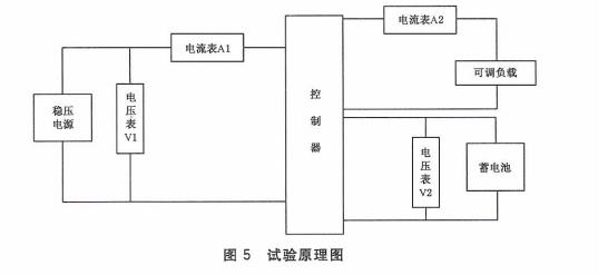
6.3 Controller
6.3.1 Test schematic
The test schematic of the controller is shown in Figure 5.
6.3.2 Appearance and Structure
Visual inspection of the appearance and structure of the controller shall comply with the requirements of 5.4.1.
6.3.3 Input Voltage Range
Test circuit shown in Figure 5, connect the DC power supply, start the system, in the matching solar array output voltage range adjustment, check the controller is working properly, the results should meet the requirements of 5.4.2.
6.3.4 DC Output Shunts
Check the output split of the DC power distribution unit. The result should meet the requirements of 5.4.3.

6.3.6 lightning protection requirements
The input surge protection device of the controller shall be inspected in accordance with the test method specified in YD/T 944-2007. The result shall meet the requirements of 5.4.5.
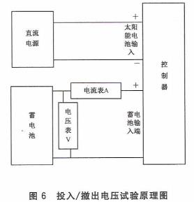
6.3.7 Input/Exit Voltage
The test circuit is shown in Figure 6. Using a DC power supply to simulate a solar cell array to charge the battery through the controller: When the battery voltage is full to the disconnect voltage, the controller should be able to disconnect the charging circuit; when the voltage is reduced to the recovery voltage, the controller should be able to reconnect the charging circuit. The voltage value shall comply with the requirements of 5.4.6.1.
6.3.8 Charge and discharge loop voltage drop
When the controller is rated for operation, use a voltmeter to measure the voltage drop of the charge-discharge circuit (including the DC power distribution unit), and the requirements of 5.4.6.2 and 5.4.7.2 of GB/T 26264-2010 shall be met.
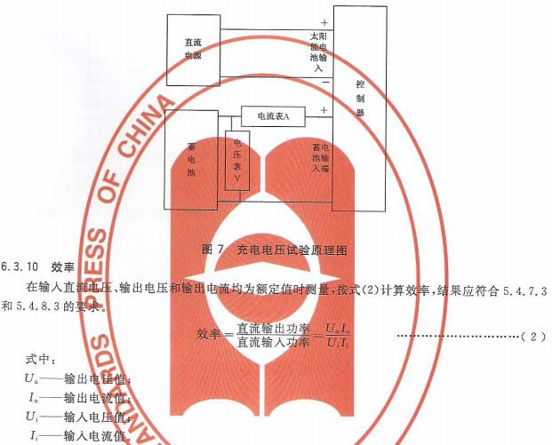
6.3.9 charging voltage
The test circuit is shown in Figure 7. Using a DC power supply to simulate a square array of solar cells to charge the battery through the controller, check the transition between the battery's average charge and float charge status, and adjust the float charge voltage and charge voltage. The results should meet the requirements of 5.4.7.1 and 5.4.8.2.
6.3.11 Temperature Compensation
Put the controller and temperature sensor into the constant temperature box, adjust the temperature of the constant temperature box to a stable state, and record the charging voltage of the controller changing with temperature. The result should meet the requirements of 5.4.7.4 and 5.4.8.4.
6.3.12 Basic Requirements for a Switching Regulator Controller
Test according to YD/T 637-2006.
6.3.13 Maximum Power Tracking Function
The solar cell array is charged by the controller to the fully discharged battery (or the device that simulates the fully discharged battery), and the output voltage and current of the solar array are respectively measured when the function is turned on and off. The result should be in accordance with 5.4.8.5. Claim.
6.3.14 No-load loss
When the controller outputs no load, the current consumption of the controller is measured with a DC ammeter. The result should meet the requirements of 5.4.9.
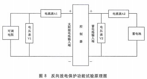
6.3.15 Reverse discharge protection
Test circuit shown in Figure 8, adjust the adjustable resistor, check whether A2 current flow, the results should meet the requirements of 5.4.10.1.
6.3.16 Overcurrent protection
The test circuit is as shown in Fig. 5. Connect the DC stabilized power supply, start the system, and adjust the load to make the controller enter the over-current state. The result should meet the requirements of 5.4.12.2.
6.3.17 Short Circuit Protection
The test circuit is as shown in Fig. 5. Switch on the DC power supply and start the system to make the controller short circuit. The result should meet the requirements of 5.4.10.3.
6.3.18 Overvoltage protection
Test circuit shown in Figure 5, using a DC power supply to simulate the solar cell square array to charge the battery through the controller, when the voltage is over the overvoltage protection value, then the voltage is returned to the recovery point; the simulated battery discharges the load through the controller when the voltage After the undervoltage protection value is reached, the voltage is returned to the recovery point; the battery overvoltage and undervoltage protection values ​​of the controller are adjusted respectively, and the above test is repeated; the result should meet the requirements of 5.4.10.4.
6.3.19 Reverse Polarity Protection
Test circuit shown in Figure 5, reverse polarity of the DC power supply, open the system, check the controller protection; check the battery circuit over-current protection device; results should meet the requirements of 5.4.10.5.
6.3.20 Impact Voltage
Test circuit shown in Figure 5, cut off the battery circuit, adjust the controller input voltage is 1.2 times the nominal open circuit voltage of the solar cell array, continuous lh, the result should meet the requirements of 5.4.10.6.
6.3.21 Inrush Current
The test circuit is shown in Fig. 5. The input current of the regulator controller is 1.25 times the nominal short-circuit current of the solar cell module for 1 hour, and the result should meet the requirements of 5.4.10.7.
6.3.22 replacement function
The test circuit is as shown in Fig. 5. Connect the DC stabilized power supply, start the system, simulate the fault or put the controller into the protection state. The result should meet the requirements of 5.4.11.
6.3.23 Monitoring Function
Check the monitoring content of the controller. The result should meet the requirements of 5.4.12.
6.3.24 Display Function
Check the display of the controller. The result should meet the requirements of 5.4.13.
6.3.25 Battery (Group) Management Functions
Check the controller's management function for the battery. The result should meet the requirements of 5.4.14.
6.3.26 Secondary Power Off
Check the secondary power-off interface of the controller's DC output power distribution unit. The result should meet the requirements of 5.4.15.
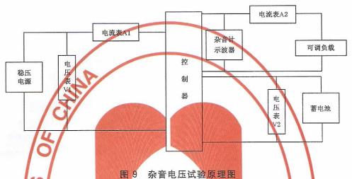
6.3.27 Noise Voltage
The test circuit is as shown in Figure 9. Connect the DC power supply and start the system. Test the following steps:
——Using the weighing weight measurement mode of the telephone in the noise meter, select 600Ω or 75Ω input impedance and appropriate range, the result should meet the requirements of 5.4.16.1;
- Use a 20MHz oscilloscope and select the appropriate range. The scanning speed is less than 0.5s. The result should meet the requirements of 5.4.16.2.
6.3.28 Audio noise
The test circuit is shown in Figure 5. Connect the DC power supply and start the system. When the controller is rated for operation, use a sound level meter to measure 1m above the controller and one-half of its height. If the measured noise at the test site is The difference in noise floor should not be less than 7dB. Otherwise, the measurement data should be corrected according to the requirements of GB/T 4980-2003. The result should meet the requirements of 5.4.17.
6.3.29 Insulation resistance
Under normal temperature conditions, the test voltage of DC 500V of the insulation resistance tester is used to test the AC circuit of the tested controller against the ground and the DC circuit. The result should meet the requirements of 5.4.18.1.
6.3.30 electric strength
Use a pressure tester to test the controller against electrical strength.
The measured controller must be tested for electrical strength before conducting insulation resistance tests and meeting requirements.
Test content: withstand voltage and leakage current (AC circuit to ground, DC circuit to ground).
Test voltage: AC circuit test voltage to ground is 50Hz, effective value is 1500V AC voltage or equivalent to its peak 2120V DC voltage; DC circuit to ground test voltage is 50Hz, AC voltage is 500V AC or equivalent Its peak 710V DC voltage.
Duration of test: The test voltage gradually increases from less than half the maximum amplitude, and lasts for 1 min when the specified voltage value is reached.
Test results should meet the requirements of 5.4.18.2.
6.3.31 Protective Grounding
The grounding performance test is carried out as follows:
A) The tested controller shall be completely disconnected from the input circuit, output circuit, monitoring equipment and all external circuits;
b) Using micro-ohmmeters such as digital micro-ohmmeters and Kelvin bridges, the external surfaces of the front and rear movable doors (boards) and their doors (boards), such as handles, buttons and key locks, may be touched. The resistance value of the connection between the metal part and the main protective grounding terminal should meet the requirements of 5.4.18.3.
6.4 Inverter
Test according to the requirements of YD/T 777-2006.
6.5 Electromagnetic Compatibility
According to the provisions of 5.5 in YD/T 983-1998, the results should meet the requirements of 5.6.
6.6 Reliability
According to the provisions of YD/T 282-2000, the results should meet the requirements of 5.7.
6.7 Environmental Test
6.7.1 Low temperature storage test
Test according to "Test Ab" in GB/T 2423.1-2008. The controller has no packaging, no power, no battery. The test temperature is (-40 ± 3) °C, and the test duration is 16 hours. After recovering for 2 hours under standard atmospheric conditions, the tested equipment should be able to work normally.
6.7.2 Low temperature working test
Test according to "Test Ad" in GB/T 2423.1-2008. Controller without packaging, without battery. The test temperature is (-5 ± 3) °C, and the test duration is 2h. After recovering for 2h under standard atmospheric conditions, the tested equipment should be able to work normally.
6.7.3 High temperature storage test
Test according to "Test Bd" in GB/T 2423.2-2008. The controller has no packaging, no power, no battery. The test temperature is (70 ± 2) °C and the test duration is 16 hours. After recovering for 2 hours under standard atmospheric conditions, the tested equipment should be able to work normally.
6.7.4 High temperature working test
Test according to "Test Bd" in GB/T 2423.2-2008. Controller without packaging, without battery. The test temperature is (40 ± 2) °C and the test duration is 2 hours. After recovering for 2 hours under standard atmospheric conditions, the tested equipment should be able to work normally.
6.7.5 Constant Humidity Test
Test according to "Test Cb" in GB/T 2423.3-2006. The controller has no packaging, no power, no battery. The test temperature is (40±2)°C, the relative humidity is (93±3)%, and the duration of the test is 2 hours. After recovering for 2 hours under standard atmospheric conditions, the tested equipment should be able to work normally.
6.7.6 Vibration Test (Sine)
According to GB/T 2423.10-2008 "Test Fc" test, the controller without packaging, no electricity, without batteries. The frequency is (10-55) Hz, the amplitude is 0.35mm, and each axis of X, Y and Z is 30min. The tested equipment should be able to work normally after the test.
7 inspection rules
7.1 Inspection Classification
Product inspection is divided into factory inspection and type testing. The factory inspection is divided into two kinds: 100% inspection and sampling inspection. You can choose one according to the situation. After the inspection is completed, fill in the inspection record and send the certificate to the factory.
7.2 Factory inspection
7.2.1 100% inspection
If one of the performance indicators fails to meet the requirements, it shall be deemed to be unqualified and shall be returned to the repair test; if the retest fails, no certificate shall be issued.
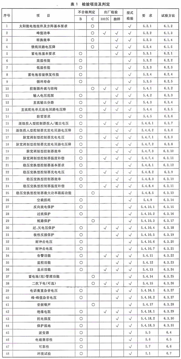
The inspection items, requirements, and test methods for 100% inspection are described in Table 1 and the relevant contents of Chapters 5 and 6.
7.2.2 Sampling inspection
Sampling inspections are carried out on a batch-by-batch basis. The level of inspections uses Level II in GB/T 2828.1-2003, and the sampling plan follows the one-time sampling plan in GB/T 2828.1-2003. The product quality is represented by the number of unqualified products; the product is unqualified and divided into B and C categories.
The acceptance quality limits AQL are: Class B 4.0; Class C15. According to AQL in GB-T 2828.1-2003 Table 2-A found that the sample size n, the number of acceptance A. And the number of rejects Re.B: n=3, A=0, Re=1; C: n=3, A=1, Re=2
Sampling inspection shall follow the transfer rules in 13.3 of GB/T 2828.1-2003; the disposal after sampling inspection shall be performed in accordance with Chapter 7 of GB/T 2828.1-2003.
The inspection items, requirements, and test methods for sampling inspections are described in Table 1 and the relevant contents of Chapters 5 and 6.
7.2.3 type inspection
Type inspections are carried out on a periodic basis, usually once a year. One of the following cases must be type tested:
A) Resumption of production after the product ceases production for more than one cycle;
b) Transfer to factory for re-testing and formulating;
c) After the formal production, if the structure, materials, processes have changed greatly;
d) Before the product is put into production or the quality supervision agency puts it forward.
Types of inspection items B, C failed, requirements and test methods in accordance with the corresponding relationship in Table 1 see Chapter 5 and Chapter 6 of the relevant content.
8 signs, packaging, transportation, storage
8.1 Logo
There must be a mark in the proper position of the product. The content, appearance and performance of the product nameplate shall comply with the provisions of YD/T 122-1997; the product packaging shall have a mark and comply with the provisions of GB/T 191-2008.
8.2 Packaging
Product packaging should be moisture-proof, vibration-proof, and should comply with the provisions of GB/T 3873-1983.
Product accompanying files:
A) product certification;
b) product specification;
c) packing list;
d) other technical information.
8.3 Transportation
The product should have an awning during transportation, and there should be no severe vibration or impact.
8.4 Storage
Product storage should meet the requirements of GB/T 3873-1983.
Silicon Manganese Alloy (High Silicon)
The Silicon Manganese Alloy,The Silicon Manganese Alloy Product,Ferro Silico Manganese,Silicon Manganese Alloy Product
NINGXIA HELANSHAN METALLURGY CO., LTD. , https://www.nxhlsyjferrosilicon.com