The bolt tightening control method is discussed from the actual situation of the torque and clamping force in the bolt connection.
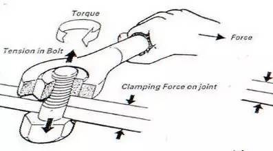
As shown in the figure above, after the torque is applied to rotate the bolt, the screw is stretched by force, and the screw is extended to generate a clamping force to clamp the connector. We know that the applied torque is not as simple as the clamping force, in the general formula:
Force (F) * torque (L) = torque M
This means that the more the bolt rotates, the greater the torque obtained. However, 90% of the torque is consumed by the friction, and only 10% is converted to the clamping force. For example, when you tighten a bolt with a process requirement of 10 N·m torque, what we really need is the 1 N·m axial moment, and most of the torque is consumed by the friction.
What is the relationship between friction and clamping force? As mentioned above, in general, following the 50-40-10 principle, 50% of the bolt head friction, 40% of the thread pair friction, 10% Clamping force. However, the ratio of clamping force can vary under some conditions.
For example, when a worker's master picks up a bolt and finds that his thread is bumped or has impurities, once you put it into the screw hole, what kind of clamping force does the bolt produce? It is generally believed that there are defects (impurities, bumps, etc.) in the thread pair. After assembly according to the assembly torque, there is 50% of the friction under the bolt head, and the friction in the 45% thread pair is only 5% of the clamping force we want. At this time, the assembly torque of this bolt is reached, but it does not meet the clamping force we need. If the bolts here are very easy to fall off on moving parts such as flywheels, crankshafts, etc., this causes what we often call "false tightness".
Also, the softening of the elastic material will attenuate the clamping force, which is also the torque attenuation that we usually say soft connections. For example, the cylinder head gasket material is soft. We use the secondary tightening method to reduce the damping of the clamping force. The clamping force of the organic oil disc bolt often occurs, because the organic oil disc gasket under the bolt (the soft material). .
Imagine that we need the screw to stretch and generate the clamping force. The longer the torque, the longer the screw can stretch. Is the torque greater? The greater the torque we apply, the excessive elongation of the bolt, and the stress breakage occurs when the bolt exceeds the yield strength limit.
Thereby losing the link function of the bolt.
In actual work, whether it is the pressing force between the two connected bodies or the axial preloading force on the bolt, it is difficult to detect and it is difficult to directly control. Therefore, the following methods have been adopted. Indirect control.
1. Torque control method (T)
The torque control method is the initial and simplest control method. It is based on the screw connection. When the axial clamping force F is tightened, it is proportional to the tightening torque T. It can be expressed by a formula T=K·F. Is the torque factor. When an screw is designed, its axial clamping force F is known. The tightening torque T is set by the process and our tightening torque is also regulated by the process department. However, the tightening torque is often reached in the assembly shop, but the assembled bolts are still unqualified. Why?
The key is the torque coefficient. The main fluctuation factor of the torque coefficient K is the comprehensive friction coefficient u. That is to say, the bolt, the accuracy of the screw hole, the impurity, and whether the bump will affect the comprehensive friction coefficient u. Moreover, this K value is also related to the temperature. After the Sumitomo Corporation of Japan passed the experiment, the torque coefficient K decreased by 0.31% for every 1 °C increase in ambient temperature. Is the torque control method accurate? To deepen the impact on everyone, according to the German Engineers Association tightening test report, when the error of the tightening torque T is ±0 (that is, the torque is applied without error), the axial clamping force error of the bolt can reach ±27.2%.
Application steps:
Direct or indirect controlled loading torque The actual target torque is typically 50% to 85% of the yield torque.
Used in tight elastic areas
90% of the load torque is used to overcome the friction preload force accuracy of ± 25%The advantage of the torque control method is that it is low cost and can be checked with a simple tightening tool torque wrench.
The disadvantage is that the tightening accuracy is not enough, the material potential cannot be fully utilized, and the environmental impact is large (temperature, bolt thread, impurities, bumps, etc.).2, torque-rotation control method (TA), also known as superelastic control method
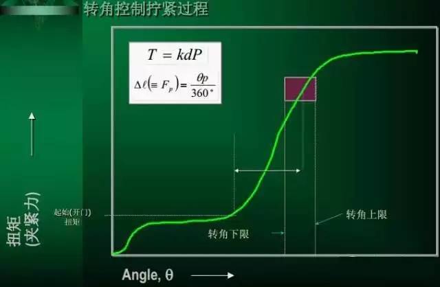
The torque-rotation control method is to first tighten the bolt to a small torque, which is usually 40%-60% of the tightening torque (established by the process verification), and then from this point, screw a specified corner control method.
This method is based on a certain angle of rotation, the snail produces a certain axial elongation and the connector is compressed. The purpose of this is to screw the bolts to the close contact surface and overcome some of the unevenness of the surface irregularities, while the axial clamping force required later is generated by the corners. After calculating the rotation angle, the influence of frictional resistance on the axial clamping force no longer exists, so its accuracy is higher than the simple torque control method. The key point of the torque control method is to measure the starting point of the rotation angle. Once this rotation angle is determined, we can obtain Quite high tightening accuracy.
Thanks to the relatively advanced tightening method, a tool for adapting to productivity is produced, which is an electric tightening tool, which is composed of a motor-driven tooth-elbow gear-sensor, etc., which can relatively easily set the warning torque and start. Corner.
Application steps:
Apply a fixed torque (starting (opening) torque)
The initial condition of the rotation of the fastening member to the predetermined angle of rotation is also used in the elastic region.
It is necessary to use the test to determine the initial (opening) torque and the corner parameter pre-tightening accuracy of ±15%.Torque-angle control method (TA) advantages: high tightening accuracy, can obtain a large axial clamping force.
Disadvantages: The control system is more complicated. It is necessary to measure the pre-tightening torque and the corner data. The quality department is not easy to find an appropriate method to check the tightening result.3. Yield point control method (TG)
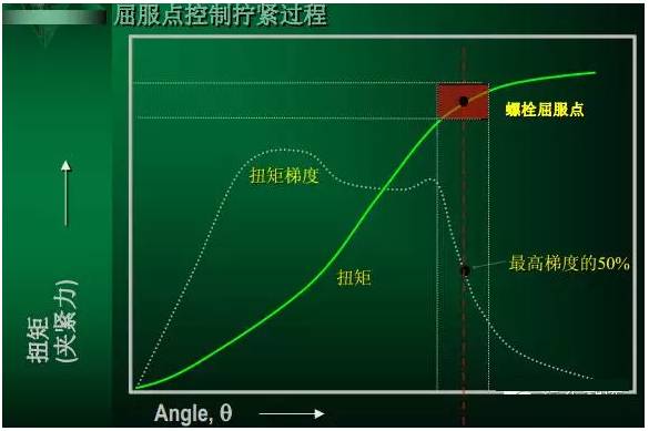
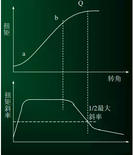
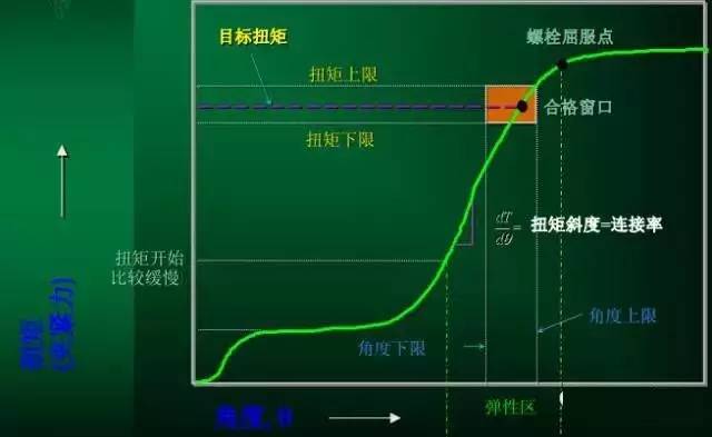
It can be seen from the above clamping force diagram that the same angle error of the bolt axial preload force error ΔF2 in the elastic region is much smaller than the bolt axial preload force error ΔF1 in the elastic region. The yield point control method is a method of stopping the tightening after tightening the bolt to the yield point. It is a high-precision tightening method developed by the phenomenon of material yielding. This control method determines the yield point by continuously calculating and judging the slope of the tightened torque/turn curve. During the tightening process of the bolt, the torque/rotation angle curve is shown in the torque and torque slope comparison chart. At the beginning of the actual tightening, the slope rises very quickly and then remains constant after a brief slowdown (a_b interval). After b point, its slope drops rapidly after a brief slow decline. When the slope drops by a certain value (generally defined, when its slope drops to one-half of the maximum value), it indicates that the yield point (ie, Q point in the torque comparison chart) has been reached, and the stop tightening signal is immediately issued. The tightening accuracy of the yield point control method is very high, and the error of the preload force can be controlled within ±4%, but the accuracy is mainly determined by the yield strength of the bolt itself.
The torque and the angle of rotation are monitored during tightening. When the maximum gradient is lowered, the maximum gradient and the yield point are utilized. The maximum pressing force is used. The friction is not reduced. The angle of the angle of the bolt is allowed to be tightened every time. The preload is not correct. ±8%
4. seating point - corner control method (SPA)
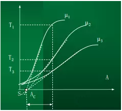
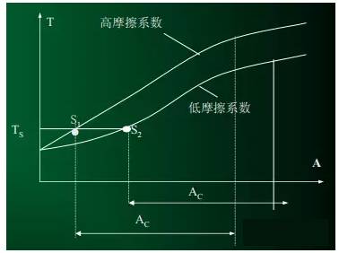
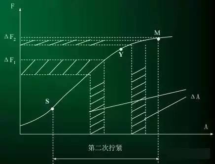
The seating point-corner control method is a newly emerging control method developed on the basis of the torque-turn angle TA method. The TA method uses a pre-torque Ts as the starting point of the corner, and the SPA method calculates the starting point of the corner, using the intersection S of the linear segment slope of the torque curve and the corner A coordinate (see figure).
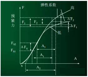
In the figure; F1 is the maximum bolt axial preload force error of the TA method, and F2 is the maximum bolt axial preload force error of the SPA method. It can be seen from the figure that when the TA method is used, the error of the pre-torque TS (ΔTs=Ts2-Ts1, corresponding to the bolt axial preload force error ΔFs), after the same rotation angle A1, relative to the two elasticity For the tightening conditions with different coefficients, the bolt axial preload force error is F1; even if the spring constant is equal, there is a certain error due to the existence of ΔTs (see ΔF1, ΔF2 in the figure). If the SPA method is used, the bolt axial preload force error is F2 because it is rotated from the seating point S to the A2 corner, and the tightening conditions are different with respect to the two elastic coefficients. Obviously, F2 is smaller than F1, that is, the seating point-rotation control method has higher tightening precision than the torque-rotation angle control method. With the SPA method, the influence of the friction coefficient on the axial preload of the bolt can be almost completely eliminated. The next figure shows the torque-rotation curve corresponding to the different friction coefficients in the tightening. The coefficient of friction in the figure: μ1>μ2>μ3. Although the slope of the torque-rotation curve corresponding to different friction coefficients is different, the seating point (the slope of the linear section of the curve and the intersection of the horizontal axis) is not much different. Therefore, an angle Ac is further screwed from this point, and the influence of different friction coefficients on the axial preload of the bolt can be basically eliminated.
The main advantage of the SPA method compared with the TA method is that it can overcome the torque error that has been generated at Ts, so the tightening accuracy can be further improved.
5. Bolt extension method (QA)
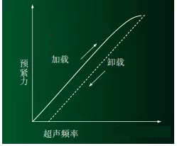
The QA method is a control method for determining whether the yield point is reached by measuring the elongation of the bolt. Although the yield strength of each bolt is inconsistent, it will bring errors to the tightening, but the error is generally very small. The method of measuring the elongation of bolts in the QA method is generally measured by ultrasonic waves, and the echo frequency of the ultrasonic waves is increased with the elongation of the bolts. Therefore, a certain echo frequency represents a certain amount of elongation. The illustration is the principle of the QA method. When the bolt is tightened and loosened, the echo frequency measured by the ultrasonic system changes with the tightening (elongation) and loosening (decreasing the elongation) of the bolt. Without coincidence, the rising frequency of the axial preload of the same bolt is lower than the falling frequency. Thus, care should be taken when measuring the yield point of the bolt.
6 Torque slope method
The torque slope method is a method of controlling the initial preload force by using a change in the torque slope value in the torque-turn curve as an index. This tightening method generally uses the yielding and tightening axial force of the bolt as a target value for controlling the initial preload. This tightening method is generally used when the initial preload force dispersion of the bolt is small and the bolt strength can be utilized to the utmost. However, since the tightening method has basically the same control of the initial pre-tightening force as the cornering method of the plastic zone, strict control of the yield point of the bolt is required. Compared with the cornering method of the plastic zone, the tightening method has fewer problems in terms of plasticity of the bolt, such as repeated use, and has certain advantages. However, the fastening tool is complicated and expensive.
Pyrite as Fillers Used in Steelmaking and Core-Spun Yarn
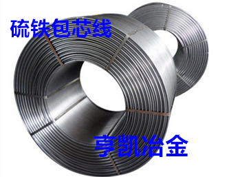
Steel-making/casting core-clad wire (filling material)
Place of Origin: Henan Luoyang, China
Pyrite, Iron pyrites, pyrites lump, Ferro sulphur, Pyrites powder.
Product Description:
Detailed introduction: is used as the filling material of cored wires and resulfurization additive agent for steel-making and casting. It is used for adding sulfur element in steel smelting to improve the cutting performance, inoculation effect, graphite shape and mechanical properties of gray pig iron.
Quality:
S: 48%min, FE: 42%min, SIO2: 3.0%max, PB: 0.1%max,
ZN: 0.1%max, AS: 0.1%max, . C: 0.3%max, CU: 0.2%max,
H20: 1.0%max, SIZE: 95%min
Granularity: (0-3)mm/(3-8)mm/(3-15)mm/(15-50)mm or other particle size.
Packing: 25KG/500KG/1000KG/BAG or 1000KG/BAG or other packaging.
Note: if there are special requirements, the product can be customized according to clients` requirements.
Iron Pyrite
Pyrite, Iron pyrites, pyrites lump, Ferro sulphur, Pyrites powder
LUANCHUAN COUNTY HENGKAI METALLURGICAL MATERIALS SALES CO.,LTD , https://www.pyritechina.com