In this paper, HyperMesh is used to build the finite element model of the framework. The main operational load is loaded into the framework with reference to the UIC615-4 standard. The stress under various working conditions is solved by RADIOSS, and the stress amplitude and average stress of the key points are calculated. Then the HyperGraph software was used to plot the Goodman fatigue limit diagram of the material and the relationship between the average stress and the stress amplitude of the key points. The fatigue strength analysis of the frame was completed according to the Goodman diagram, and the conclusion that the fatigue strength of the frame was qualified was obtained.
1 Introduction
The bogie is one of the important components of the subway vehicle. It directly carries the weight of the car body and ensures that the vehicle passes smoothly through the curve. At the same time, the various parameters of the bogie also directly determine the stability of the vehicle and the ride comfort of the vehicle. The frame is used as the basis for the installation of the remaining components of the bogie, not only to transfer the weight of the car body and the vibration load during operation to the wheel pair, but also to the various loads generated by the traction, braking and suspension system components connected thereto. . Due to the complex force state of the frame, it is necessary to evaluate the fatigue strength of the frame during the design phase of the bogie. This paper takes the structure of the subway car bogie as the research object, uses Altair's HyperMesh software to build the finite element model of the framework, and uses the RADIOSS solver software to solve the stress of the frame under several typical working conditions, and calculates the stress at the key point. The amplitude and average stress were calculated according to the Goodman diagram of the material.
2 finite element model of the framework
The bogie frame is a fully enclosed welded structure. It is mainly composed of two side beams and two beams. The frame side beams are generally U-shaped box-shaped welded structure. The lower sides of the frame are provided with rubber spring mounts on the lower side, and the upper part of the center is provided. Air spring mount. The frame beam also adopts a closed box-type welded structure. The motor hanger and the gear box hanger are arranged obliquely symmetrically outside the beam, and the traction symmetry position of the lower side is provided with a traction rod seat, and a lateral stop between the two beams is provided. seat. There are also multiple ribs in the beam and inside the measurement to enhance the strength of the frame.
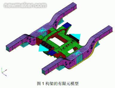
The finite element model of the framework established by HyperMesh software is shown in Figure 1. In the finite element modeling process, the actual structure is discrete according to the structure. Except for the solid parts of the motor hanger and the gearbox hanger, the rest of the structure uses the board unit. Discrete. Considering the influence of motor inertia on the strength of the frame, a node is established at the center of mass of the motor, which is connected to the motor hanger by a rigid unit. A total of 24,454 nodes and 23,553 units are separated, of which 5,136 are physical units and 18,417 are board units.

3 Load calculation and working conditions
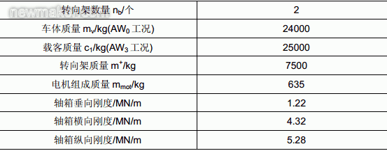
The operational static load calculation parameters of the framework are shown in Table 1:

3.1 Main operating conditions load
3.1.1 Vertical load
According to the UIC615-4 standard, the vertical load of the main operating conditions is:

The vertical load acts on the air spring mount of the side members.
3.1.2 Lateral load
According to the UIC 615 4 standard, the lateral load of the framework is:
The lateral load acts on the lateral stop.
3.1.3 Twisted load
The torsional load simulates the warpage of the bogie frame in the case of twisting of the line, acting on a series of spring mounts, with one diagonal direction upward and the other diagonal direction downward. According to the literature [2], the torsional load of the frame is :

3.2 Main combination calculation conditions
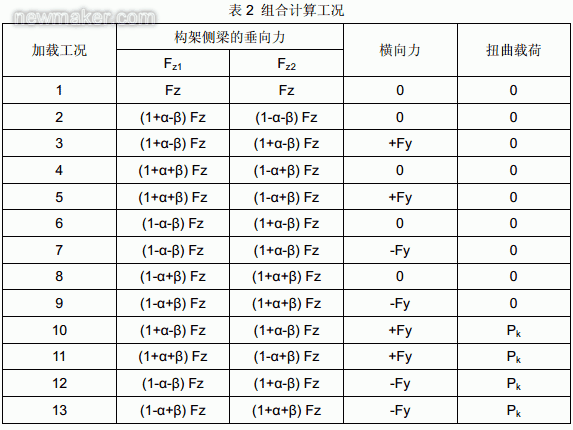
Considering the change of the vertical force caused by the vibration of the vehicle body, the vertical force percentage is β = 0.2, considering the change of the vertical force caused by the rolling of the car body, the percentage of the vertical force is α = 0.1, according to the UIC 615 4 standard. The combined operating conditions of the main operating conditions are shown in Table 2:

4 Fatigue strength calculation results and analysis
The research organization of the International Union of Railways UIC recommends using the Goodman fatigue strength curve method to assess the fatigue strength of the frame. The evaluation principle of this method is within the specified range of the stress amplitude and average stress of the nodes on the frame. The formula for calculating the stress amplitude and the average stress is:

The stress distribution of the RADIOSS solver architecture under the above 13 conditions. According to the structural characteristics of the frame, the five points with high stress and fatigue cracking are selected as the fatigue strength evaluation sampling points: the first point is the upper cover at the junction of the side beam and the beam, and the second point is the junction of the side beam and the beam. The lower cover, the third point is the upper left corner of the gearbox hanger and the crossbar, the fourth point is the lower right corner of the gearbox hanger and the crossbar, and the fifth point is the left corner of the upper cover of the motor hanger. The fatigue strength stress calculation results of each sampling point are shown in Table 3:

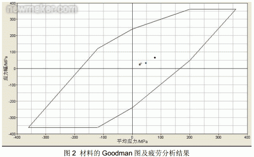
The material of the frame is low-alloy high-strength steel, the yield limit is 360Mpa, and the fatigue strength is 240Mpa. The Goodman diagram of the material drawn by HyperGraph software and the average stress and stress amplitude of the sampling point are shown in Figure 2:

It can be seen from Fig. 2 that the stress range of each sampling point is within the Goodman fatigue limit range, indicating that the frame meets the fatigue strength requirement.
5 Conclusion
The finite element model of the framework was built with HyperMesh software, and the load under the main operating conditions was loaded into the framework according to the UIC615-4 standard. Then the stress of the frame under various working conditions was solved by RADIOSS software, and the stress amplitude of each key point was calculated. And average stress. According to the performance parameters of the material, the Goodman fatigue limit diagram of the material and the relationship between the average stress and the stress amplitude of the sampling point were plotted by HyperGraph software. The conclusion that the fatigue strength of the frame is qualified is obtained by the Goodman diagram.
6. References:
[1] Ye Hongyan, Qi Pingbo. Static strength analysis and fatigue strength evaluation of welded frame of bogies [J]. Railway Locomotives. 2011(2), 23.
[2] Zhang Binyu, Zhao Honglun.Optimization Design of Metro Car Steering Frame Based on Finite Element Analysis[J].Computer Aided Engineering.2011,20(2),82-85.
[3] Zhang Shuhuai, Li Yongchun, Sun Junshuai. Calculation and Analysis of Finite Element Strength of Metro Vehicle Steering Frame[J].Machinery Design & Manufacture.2009,(1),45-47.

Concerned about surprises
Tag: Fatigue strength, bogie, side beam, working condition, beam
Previous: Ultrasonic level gauge principle and installation requirements Next: Protect the car cooling fan module from thermal runaway
Titanium Dioxide,Hot Saled Titanium Dioxide,Titanium Dioxide Rutile
Titanium Dioxide Rutile Grade Co., Ltd. , http://www.hengchangchemical.com