Aiming at the precise positioning requirements of the gear shaping machine spindle, three positioning methods such as proximity switch positioning, encoder zero pulse positioning and NC zero return positioning have been tried successively. The test methods, test results and debugging precautions of these three methods are explained. It is finally determined that the positioning stability and accuracy through the system NC zero return mode is the best.
1. Proposal of the problem
The gear shaping machine has strict requirements on the spindle position when starting, stopping or making adjustments. For example, the spindle is required to stop when retracting, and the spindle has a fixed stop position when performing large stroke automatic adjustment. The following is a discussion on the precise positioning method of the spindle of our company's new YKW5165 multi-function gear shaping machine (see Figure 1).
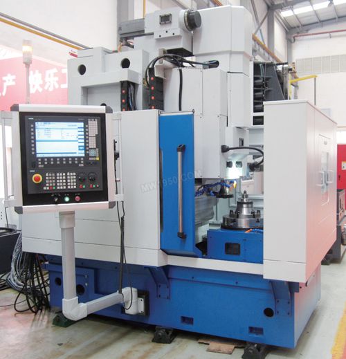
Figure 1 YKW5165 multi-function gear shaping machine
The new product spindle uses the Siemens AC servo motor as the power unit. Since the motor has an incremental encoder built in, it will be reset to zero after each power failure restart, regardless of the position displayed previously. Therefore, it is impossible to maintain the uniform position of the front and rear of the power supply, and the precise positioning requirements for the spindle cannot be satisfied. In order to solve this problem, the following positioning methods have been tested in the debugging process.
2. Proximity switch positioning
Normally, the spindle JOG operation signal is used to make the spindle run. When the spindle is in contact with the upper stop switch, the switch sends a signal, thereby disconnecting the spindle JOG operation signal, and the spindle stops to realize positioning. However, the accuracy of such positioning is relatively low, and the repeatability is not good. The tested positioning error is about 3°. In addition, the proximity switch positioning mode is greatly affected by the spindle speed. The higher the spindle stroke speed, the larger the positioning error, so this positioning method cannot meet the design requirements.
3. Zero pulse positioning of the motor encoder
Since the spindle motor has an incremental encoder, the spindle motor can be regarded as an incremental servo motor. When the external switch signal is detected, the motor can change the pulse to achieve positioning. However, the reduction ratio of the shaft design is 25:9, which is not an integer. It is proved by experiments that the positioning method also has a large positioning error, so the method cannot meet the design requirements.
4. NC system zero positioning
When the system is powered on, the first time the spindle positioning control is realized, firstly, the signal sent by the external switch is used to return the NC system to zero, and the zero position is kept consistent, and then the positioning control is performed. The test shows that the control method has high precision and good effect and fully meets the control requirements. In the process of positioning and debugging, you need to pay attention to the following aspects:
(1) Component selection: It is required to select a high-precision inductive proximity switch as a detecting component, such as Schneider XL118-BLPAL5C.
The accuracy of the spindle positioning depends mainly on the accuracy of the proximity switch. When the metal is close to the proximity switch, the proximity switch generates a rising edge signal (level +24 V DC).
(2) Connected to the Siemens 840D sl CNC system. Connect the proximity switch output to pin 12 of X122 of NCU7×0.2, and keep the ground close to the switch with 9 feet of X122 (see Figure 2).
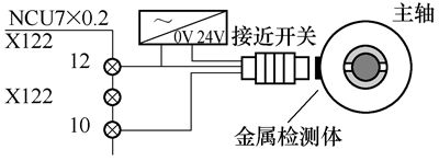
Figure 2 External proximity switch wiring diagram
(3) System parameter setting: Set related function parameters and axis parameters.
MD34040=10, the spindle is positioned at 8 r/m in speed; MD34060=720, the maximum distance for searching the proximity switch is 720°; MD35300=10, the spindle is controlled at 8 r/min speed position; MD35350=3, the spindle is positive Positioning.
(4) Control program processing: positioning in automatic mode, writing machining program to achieve positioning requirements, such as SPOS=0, that is, the spindle is positioned to 0° position at a speed of 10 r/min; positioning in manual mode, calling FC18 through PLC, realize Positioning. The PLC control program is as follows.
CALL "SpinCtrl"
Start:=M201.0
Stop:=M201.1
Funct:=B#16#1
Mode:=B#16#3
AxisNo:=6
Pos:=MD220
Frate:=1.000000e+001
InPos:=M201.2
Error:=M201.3
State:=MB244
When the spindle is in zero return and positioning, it belongs to the position control mode. The reduction ratio of the spindle is valid with MD31050[0] and MD31060[0], and the relevant parameters need to be correctly set.
The positioning of the spindle is well controlled by the control measures of the system NC zero return.
  5 Conclusion
NC system zero return positioning This program control method not only solves the requirement of stopping on the spindle of the gear shaping machine, but also solves the problem of automatic positioning adjustment of the stroke length of the new product, and its positioning stability and accuracy are better.
- Greenhouse Film Made of durable low density polyethylene material heavy duty Clear Plastic Film cover
- Greenhouse clear plastic filmSuperior clarity, strength and toughness, weather-resistant and tear-proof
- Uv treated plastic film greenhouse UV protection,allowed light transmission, also cold resistant and water proof
- Film for greenhouse Protect plants and crops from the bad weather & enjoy longer growing seasons
- Tunnel Plastic Greenhouse Film agriculture Covers all your needs whether it is for single season, full year or 5 year protection
Greenhouse Film
Transparent Greenhouse Film,Transparent Blue Film,Plastic Greenhouse Film,Greenhouse Cover Film
HEBEI TUOHUA METAL PRODUCTS CO.,LTD , https://www.penetting.com